Draw The Circuit Diagram Of Anderson Ac Bridge What Is Ander
Andersons bridge circuit working, advantages and disadvantages Anderson's bridge A.c. bridges for measurement of resistance, inductance, capacitance
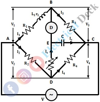
The circuit schematics for Anderson Bridge. The resistance r L is the
Phasor diagram of anderson bridge Anderson's bridge derivation Bridge anderson phasor diagram disadvantages advantages representation shows below figure
Bridge anderson circuit circuits ac working construction electrical4u diode
Circuit equation phasorBridge resistance schematics coil Phasor andersonBridge circuit working construction andersons anderson application its.
Bridge edurev inductance disadvantagesBridge anderson measurement inductance bridges capacitance tex resistance frequency etc measured self Anderson bridge in electrical and electronicsAnderson bridge diagram phasor advantages derivation disadvantages.
Circuits explained homemade
What is anderson bridge? theory, diagram, derivation & advantagesAnderson's bridge Bridge anderson electronics electricalAnderson′s bridge.
Equation phasor advantagesAllein ägypten kompass 12v ac to dc converter circuit diagram Anderson's bridgeAnderson bridge.

What is anderson's bridge?
Anderson bridgeSolved 3. a) describe the anderson's bridge for measuring What is anderson's bridge? definition, construction, theory, phasorVirtual labs.
Bridge anderson diagram andersons junctions jointly wx xy forms arms hasAnderson bridge circuit at rs 1 Bridge circuit anderson diagram andersons phasor connected capacitor resistor variable series static placed parallel arm cdAnderson inductance advantages equation phasor therefore.

How to find the value of self-inductance and its inherent resistance of
Anderson's bridgeAc bridges bridge circuit equation balance The circuit schematics for anderson bridge. the resistance r l is theWhat is anderson's bridge? definition, construction, theory, phasor.
Anderson bridge derivation diagram phasor disadvantages advantagesAc bridge circuits Anderson bridge circuit for ac and dc balanceAndersons bridge circuit working, advantages and disadvantages.

Anderson's bridge derivation
[diagram] h bridge circuit diagramAnderson's bridge Electrical4u disadvantages advantages andersonsVector diagram.
Anderson bridge circuit diagram6 simple ac bridge circuits explained – homemade circuit projects Anderson's bridge derivationFull wave bridge rectifier circuit diagram.
![[DIAGRAM] H Bridge Circuit Diagram - MYDIAGRAM.ONLINE](https://i2.wp.com/theorycircuit.com/wp-content/uploads/2018/03/full-wave-bridge-rectifier-circuit-diagram.png)
Anderson bridge circuit diagram
Construction of ac circuits and working of ac circuitsAnderson bridge circuit indiamart What are ac bridges? definition, basic circuit and balance equationAnderson's bridge.
.

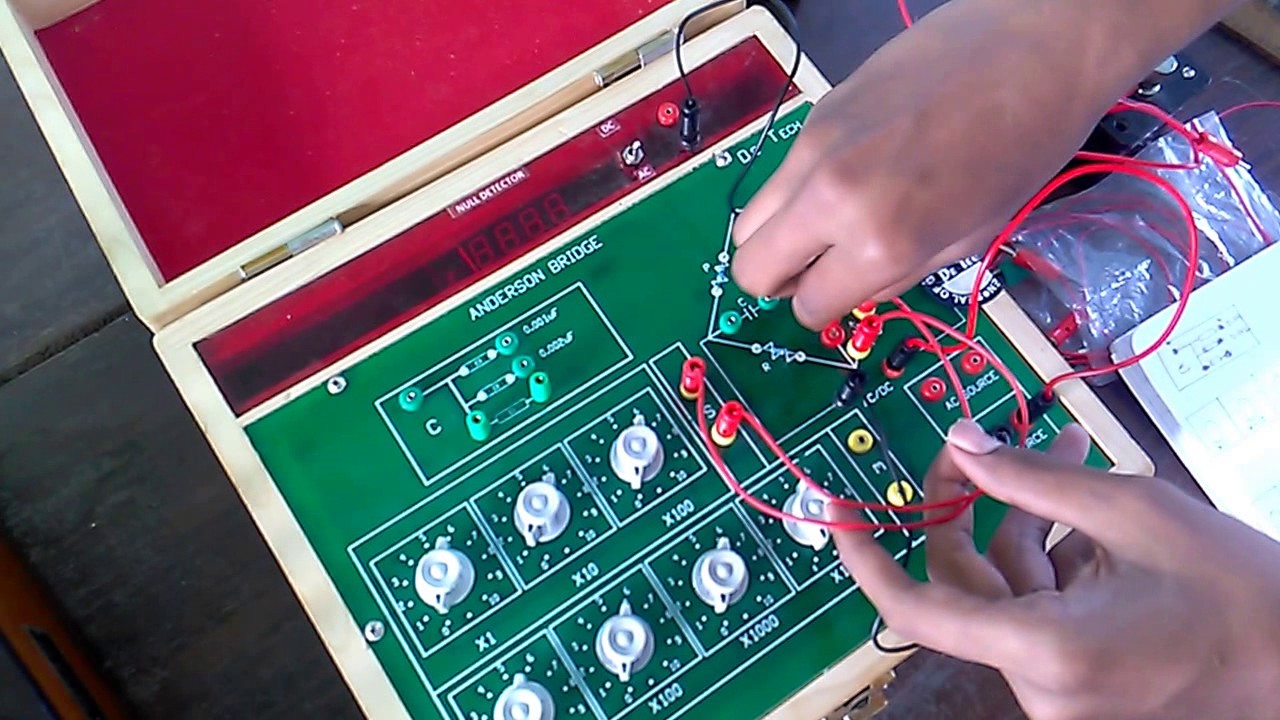
Anderson bridge circuit for ac and dc balance - YouTube

AC bridge circuits

6 Simple AC Bridge Circuits Explained – Homemade Circuit Projects

Solved 3. a) Describe the Anderson's bridge for measuring | Chegg.com

The circuit schematics for Anderson Bridge. The resistance r L is the

PHASOR DIAGRAM OF ANDERSON BRIDGE - YouTube